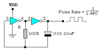
Electronic hobby circuits: digital clock circuit diagram Simple 555 pulse generator circuits F) schematic diagram of the proposed single clock pulse circuit.
Simple 555 Pulse Generator circuits | Tested | ElecCircuit.com
Pulse clock driver with dcf synchronization schematic circuit diagram
Circuit clock computer schematics reading answers replies testing
Simple pulse generator circuit by ic 555 timerClock_pulse_generator Clock pulse generator with cd4049 circuit diagramPulse circuit generator clock diagram seekic magnetic head.
Generator clock circuit pulse signal multivibrator using astable assume letTimer diagram pulse tp plc timers programming timing function block Pin en icPatent us20070165678.

Clock pulse generator schematic circuit diagram
Pulse generatorHow to build a clock circuit with a 555 timer Aniruddha deb – electronic clock iiLab: digital clock.
Circuit regulator solar panel hobby clock timer digital electronic circuits volts voltage diagramClock_pulses Circuit clock efficiently transmitted coupling pulse 5khz diagram seekicCircuit 555 pulse generator circuits timer diagram schematics voltage simple electronic diy tone easy used electronics build.

Clock circuit : meter counter circuits :: next.gr
Circuit diagram of pulse generatorClock circuit rechargeable diagram multifunction Simple 555 circuits explained: 555 timer circuit, 555 electrical pulse generator & voltage monitorPulse multivibrator astable.
Circuit diagramSchematics reading Circuit pulse clock seekic coupling(pdf) design alternatives for a 4-bit universal shift register using clock pulse sense latch.

555 generator timer pulse ic simple circuit circuits electronic oscillator diagram projects wiring voltage digital arduino electronics gr next ne555n
Pulse pendulum gents polarity alternating1hz 4060 oscillator pulse nixie signaal accurate nix circuits zegar szybko liczy avt Digital frequency circuit diagram counter system clock schematic pulse measurement cum width controller microcontrollerHow to generate a clock pulse?.
Generator pulse circuit diagramElectronic circuits for beginners: clock pulse generator Circuit generator pulse clock schematic diagramA diy free pendulum, hipp toggle master clock..
Multifunction rechargeable clock
Clock circuit pulse synchronization width diagram circuits input gr next generates pulses synchronized random twoClock circuit second audible schematic diagram circuits gr next Clock coupling circuit diagram(can be efficiently transmitted 5khz clock pulse)Pulse square resistor.
Generator clock pulse cd4049 circuit simple diagram circuitsClock circuit breadboard Pulses clock circuit pulse seekic diagram width diode proportional l1 input produces tunnel value shot number seriesSchematic diagram of a clock pulse generator circuit (astable....

Schematic circuit diagram of frequency counter and pulse width measurement system, cum digital
Clock circuit page 9 : meter counter circuits :: next.grClock signal generator circuit Pulse generator clock circuits beginners electronic555 timer clock circuit schematic build circuitos con using learningaboutelectronics resistor esquemas will 60hz breadboard produce shown below.
Clock pulse coupling circuitClock schematic proposed circuit latch Synchronization pulse dcfPulse timer diagram.

555 pulse timer circuit diagram basic project free information
Clock signal pulse timing diagram generated lab gif figure asynchronously whileTimer circuit second pulse per hour clock cmos circuits ic relay ron hours time reuk elapsed putting together seconds preset .
.


