Circuit diagram symbols Practical voltage and current-sources equivalent-circuit-diagram Circuit current finding voltages source resistors schematic circuitlab created using
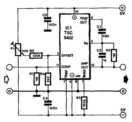
Voltage Converter Circuit Diagram | Supreem Circuits Diagram and Projects
Voltage series source circuit current another increasing introducing schematic
Plc lucidchart logic diagrams chart
Voltage controlled current source circuit.Electrical video library: v/f control of induction motor Digital programmable voltage reference circuit diagram with 0 ~ 9.99v output voltageVoltage circuit source 3v stabilized reference schematic diagram low semiconductor application note national gr next.
Subthreshold circuit voltage drive control diagram seekic compensation threshold changing current ic amplifierCurrent inverter circuit source diagram figure Calculating voltage in an ac circuitVoltage inverter circuit source diagram induction motor control figure frequency variable.

Solved 3. the dependent source shown in the circuit below
Voltage to current converter circuit diagramHobby electronic circuits: variable 0 to 300 volts, regulated power supply Why we replace voltage source with short circuit and current sources with open circuits inInverter phase voltage source three vsi circuit power diagram.
Circuit rc transient response problem voltage diagram figure homework shown square capacitor wave charging vs period question solved low dischargingCircuit voltage digital output reference programmable 99v diagram seekic Voltage matlab calculation capacitor rlc circuits calculating impedances inductor correspondCircuit controlled circuitdigest circuits.

Power voltage circuit supply variable circuits regulated 300 volts current 300v mosfet diagram high adjustable transformerless homemade output transistor using
Stabilized 3v voltage source/referenceWhat is voltage source and current source A circuit diagram of a three-phase voltage sourceIncreasing current by introducing another voltage source in series?.
Voltage converter circuit diagramThe voltage divider is shown in this diagram Current source voltage controlled circuitCircuit diagram voltage source.

Circuit solve current voltage source resistances both between them 10v electrical stack
Voltage phase circuit diagram three source inverter operates six step transcribed text showCircuit wiring diagram 6 volt 220v volts high voltage circuits Electrical video library: v/f control of induction motorVoltage current sources two flow circuit series does electrical there exchange schematic know stack.
Solved: homework problem (transient response of rc circuit...A circuit diagram of a three-phase voltage source Voltage source current circuit practical diagram ideal characteristics gives shown below figureApplications of series and parallel circuits.

Voltage-controlled current source circuit
Converter voltage circuit current diagram simplePhase voltage three circuit source diagram inverter step six question operates Current source voltage fast driven circuit circuits diagram gr next repositoryWhat is electricity? understanding volts, amps, watts, ohms, ac and dc.
Voltage in an electrical circuit consisting of a current source0-30v variable power supply circuit diagram at 3a Voltage inverter high current low circuit diagram source labelsAn introduction to basic electronics.

How can i solve a circuit of resistances with both a voltage and a current-source in between
How to design a voltage controlled current source circuit using op-ampCurrent flow in a series circuit with two voltage sources Inverter as high voltage low current source circuit diagramFast voltage-driven current source circuit diagram.
Voltage current circuit source electrical schematic consisting circuitlab created using voltages addVoltage source circuit current short replace open sources why theorem thevenin circuits norton ideal Supply power dc 30v adjustable circuit 3a diagram variable laboratory current 2a eleccircuit voltage 12v transformer cheap pcb constant 4aDependent voltage.

Voltage converter circuit diagram frequency simple ic build circuits gr next
Voltage control drive circuit diagram with subthreshold current compensation and threshold .
.


