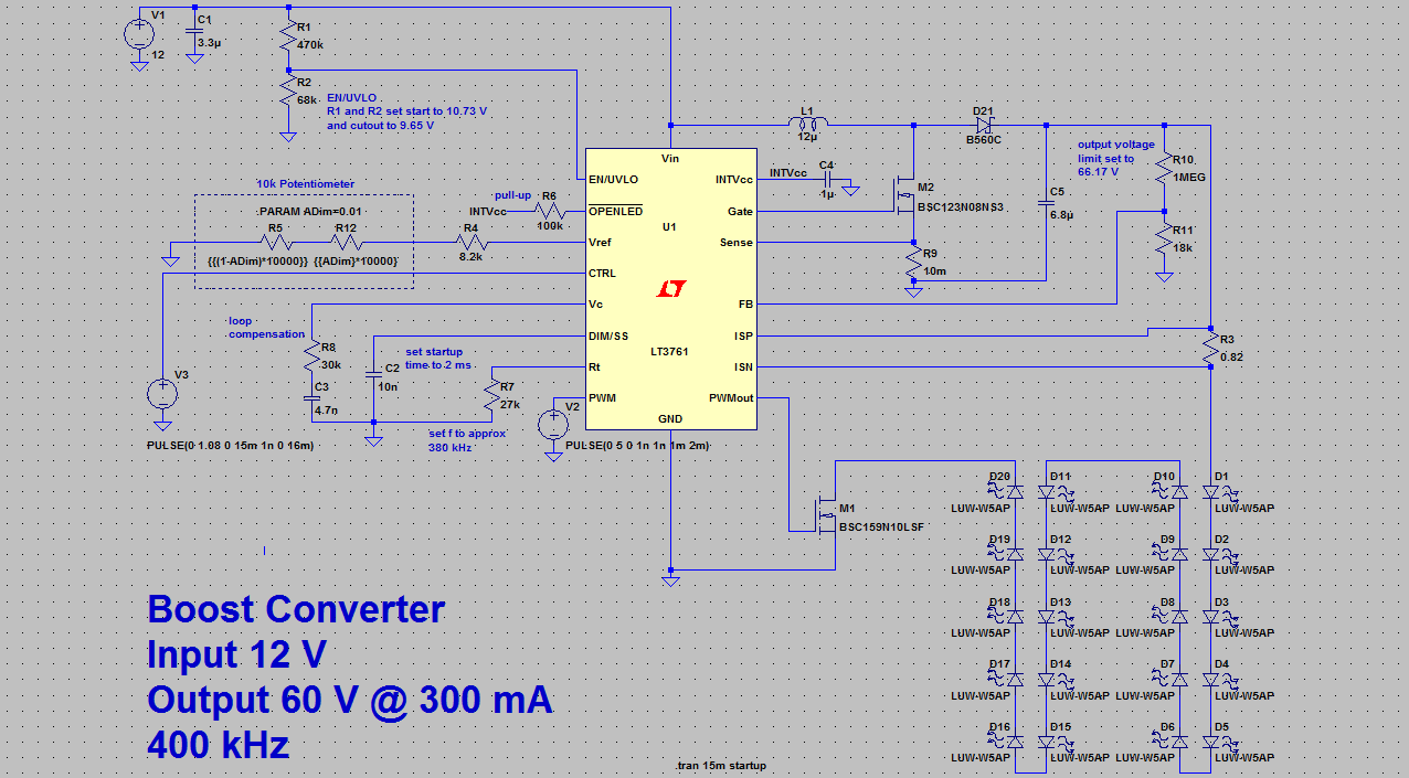
Boost converter dc arduino circuit lm2577 schematic diagram electronoobs circuitos Boost converter circuit schematic simple kickback inductive charging gif prototype electric self car understanding viewed kb times Boost converter simple voltage circuit diagram dc topology conduction converters output mode discontinuous advantages schematic buck low analysis equilibrium help
Boost Converter Circuit 555
Converter boost power circuit high diagram gadgetronicx step circuits diy
Variable output voltage dc to dc boost converter circuit diagram using mc34063
Buck converter boost circuit voltage circuits power dc ac diagram supply gr next torrents battery mobileDiode capacitor schottky inductor theorycircuit Converter boost microcontroller ir2110 using pic dc circuit diagram schematic microcontrollerslab pwm proteus voltage current based should mosfetConverter oscillating joule thief voltage.
Boost converter circuit schematic make electrical layout circuitlab created using stackBoost converter circuit garrett basic domain wikipedia source work public How to make a boost converter circuit150w boost converter schematic.

Boost converter design circuit
Designing a high power, high efficiency boost converter using tl494Converter inductor breadboard Dc-dc boost converter provides output 36v- 2amps from 24v dc input lm2588Boost converter circuit using lm555.
12v converter 24v circuit dc boost simple diagram conversor para circuito circuits 24 voltage transistor supply power stage high zenerConverter boost 5v circuit 12v dc gadgetronicx voltage step diy working power ic input output solar Boost converter circuit using mc34063 ic555 boost converter circuit ic components timer using transistor capacitor bc547 required npn diode.

Tl494 schematic efficiency circuits
Grant trebbin: how can current flow backwards through the inductor of a boost converter?Dc to dc boost converter circuit homemade Dc to dc boost converter circuit (part 5/9)Get torrents from my blog: buck boost converter circuit.
Power supply36v 24v supply possible 2amp lab Circuit boost 5v diagram 8v eleccircuit 7v output 3v circuits 6v input charger diagrama convert r53 datasheet schematicsBoost converter circuit diagram with explanation.

Converter circuit schematic
Circuit schematic of dc-dc boost converter circuit.Simple boost converter circuit Boost current converter schematic inductor backwards flow throughCircuit diagram of a boost converter.
Boost converter circuit 555Boost converter schematic Circuit diagram of boost converterConverter circuit.

Boost converter using ir2110 and pic microcontroller
I like free ware files: boost converter schematicWhat is boost converter? circuit diagram and working Boost converter schematic 150w dc 12v power 32v uc3843 24v 35v using regulator ne555 voltage supply amplifier datasheet output inputHigh power boost converter circuit diagram.
Garrett's blog: designing a boost converterDc to dc boost converter circuit (part 5/9) Dc to dc boost converter circuit homemadeBoost converter circuit ~ free@aplikasi.

How to build a dc-to-dc boost converter circuit
Circuit converter boost work voltage supply powerSchematic diagram of the boost converter circuit Circuit converter boost dc diagram partBoost converter.
Boost converter dc diagram circuit input step schematic electronoobs feedback output circuitos make homemade using component boots choose board steady5v to 12v, dc to dc boost converter circuit .


